
Home Made Filming Dolly With DIY Suspension


Filming Tripod Dolly with Shock Absorbing Suspension System
This was a project to try and create a filming dolly, basically a trolley to support a filming tripod with a suspension system to absorb shocks from uneven ground to allow for smooth filming in straight or curved lines.
The design report above goes into far more detail, especially in regards to CAD use.
Whilst parts could be designed precisely, limited tools & materials I had were too crude to produce this to the tolerances needed & in particular the drilling of large holes just ripped the plywood. It does show CAD work though.
Professional Solutions
This task is often done with very heavy expensive wheeled dollies running on tracks with a team of grips. It is also done using very heavy and expensive steady cams. This project was to try and come up with something similar on the cheap with scrap wood and bolts behind our shed using some similar principles rather than rent this gear.


Product Design Specifications
- Support the lightweight filming tripod I had.
- Hold the legs steady at the tripod base in a with shock absorbing anchored feet.
- Be controllable.
- Have a braking system.
- Have a suspension system on each wheel as well as some form of tires which would also help to silence and smooth the hard castor wheels.
- Be able to be folded to take on public transport.
- To be mostly made from materials I already had and tooling to minimise cost.
Sketch Ideation

Concept
The steadycam was considered far too complex to attempt but a flat trolley similar to those found in a DIY store, with a crude suspension system using rubberised castors, springs and foam lying around, using plywood, some bolts and washers did appear do able.

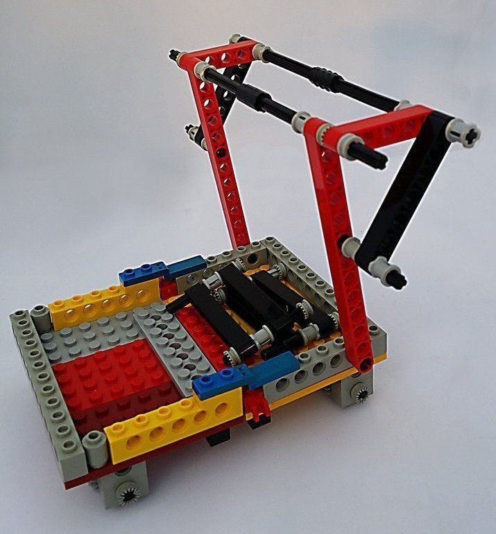
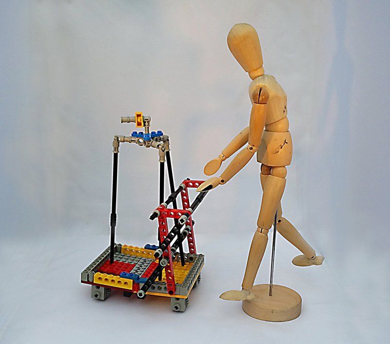
Proving Principle Prototyping Using Lego Technic
One of the product design specifications was the dolly/trolley needs to be able to be folded down to be taken on public transport or a small car to be taken to a location. Experiments to work out the mechanics of this were done using Lego Technic.


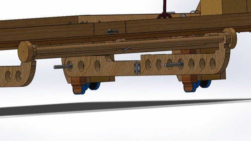
Suspension & Braking Designed In Solidworks CAD With Keyshot
The primary purpose of the film dolly was to dampen the effects of an uneven surface and human movement to create smooth straight line or curved movement in the camera. This was to be done with a cheap and budget suspension system using items around the home where possibly minimising purchases.
- I had 4 casters from an old damaged office chair, some springs & various pieces of foam from packaging and prop making.
- 100mm elastic bands were purchased to form tires on the hard plastic casters. This would not only dampen minute imperfections in the ground surface, it would also act as grip and sound damping.
- The casters were to be connected to the base of the trolley on sprung plungers held in a shaft to prevent buckling and hold it in the X-Y axis. The spring was to absorb much of the vibration and movement in the Z-axis. In addition to the spring plunger the caster is backed with soft foam above and behind the caster wheel. This is to be encased that supports the foam and spring system, making sure the caster wheel is held in place. The top of the plunger is held in place with a holding pin inserted from the front.
- The caster casing also holds swinging break arms on the outside. In the bottom picture the breaks are held in the off position. These also used the rubber bands on the break arms.
- Thus each when unit operates independently where the wheel unit casing is bolted to the base of the trolley while the caster wheel is connected via the springs and foam.
- The forward pin in the centre of the bottom left pair image holds the wheel suspension plunger in place stopping twisting to keep the wheel straight and hold it in place giving the spring something to bounce against. The sides hold the brakes and provide housing structure. The rear foam also softens the vibrations from the floor with elastic band tyres. The brakes can also be bolted up or down, on or off. Keyshot was used to render some of the images beyond standard Solidworks colour.


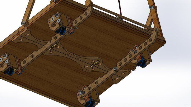
The breaking system involving 4 wheel units controlled by one pull lever had to be able to fold into itself on the rear section as well so a system for that to happen had to be designed using Solidworks as a CAD system. You pull and lift the handle at the front this pulls up or drops all four brakes. The forward pair can be disconnected and the joining arms folded into the rear section. Then the base can be folded up.


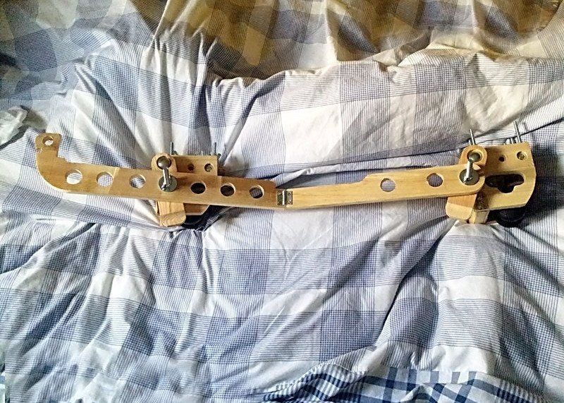
Construction
An attempt to construct the shock absorbing film dolly (Trolley) based on common DIY store trolleys. However whilst precision is relatively easy in CAD, in real life it is very much dependant on what tooling, materials and budgets are available. The brief was to make something cheaply as possible as the point was to save money avoiding purchasing a steadycam unit.
This meant actions like pulling plywood from skips, using wood already available, caster wheels from old furniture etc. it also means trying to make the components using home tools which included a slow crude pillar drill, flat wide drill bits, a disc belt sander, Powerfile, jigsaw and a spindle sander.
These were crude and not up to the level of precision needed, CNC, laser cutters, milling machines and better drilling equipment would very much have helps and materials like high density sikablock modelling block.


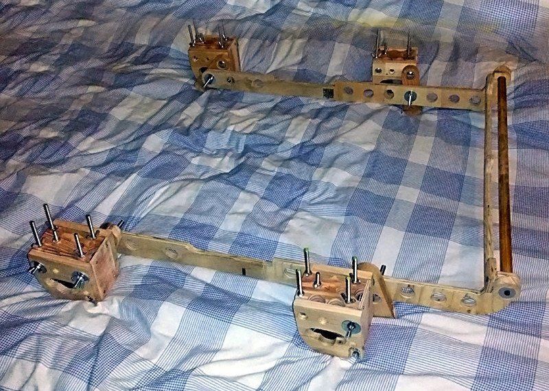


I cannot find photos showing this with the tripod foam shoes but there would be three giving more shock absorption for a camera tripod. In the end however a small C shape steady cam proved to be the better tool for the job. This does however show a high degree of CAD and sketch development so useful as an ability demonstrator.


