Star Wars Prop - Base Hacker System
Communication Tower Upgrade Aug 24


Upgrading the Communication Towers
The Communication Towers Component Parts Have Wery Weak Connections and Keep Breaking
The aerials or communication towers were loosely put together in layers glued together, but lacking a interlocking structure or more so a central spine / tang all the way through the towers the act like Lego. They break apart like layered Lego thats not interlocked. In fact, they break simply by opening the wings hard or any knocking against anything such as the roof of a car when placing it in the car as cannot handle any sheer force.
- Many of the layers had vary little surface areas to glue and little if any interlocking so for the most part different glues were not helpful.


- I needed replacement with a system with a full-length core, ideally a metal rod running though all the parts into the superstructure of the tower.
- What would be ideal would be a system there the communication towers are solid when in place but can be removed for transportation & storage.
The red component towers are parts I got from Prop House Bob's Bits.
They also need more detail.
Sides and interior Lack Kitbash Detail
The sides lack any details and need kit bashing.
Taking Apart the Existing Communication Towers Without Damaging the Base
I also had to take apart the communication towers on the towers very carefully, to avoid damage to the lower parts which were more solid.
I was also trying to work out a way to run a threaded shaft through the dead centre.
This involved very careful drilling.
I started by trying to break a glued square connection at the base of the tower by tapping a thin screwdriver into the glued joint to try and crack it.
The removed central shaft looked like it was worth keeping.
Having released the upper section, I tried to drill down into the central nerf gun multi shot clip disc base,
This has a revolving pivot inside I wanted to keep but also had to drill through.
I did not have a pillar drill so had to do this very carefully and slowly to avoid breaking the parts using a step drill bit to do one diametre at a time more gently.
I tried to use a step drill but the problem was there was a rivet and a spring in the centre which I had to drill through and push out. This left an interlocking set of shafts.
Once there was a hole running though 9mm I used a 10mm tapping kit to make a sewed threaded shaft.
Later I used a dowel making hollow drill bit to remove the centre having managed to extract the central screw instead with more success.


Taking Apart Tower 2
Having worked out a much more refined down component combination for the communication towers I then started to take part the second tower in a safer and more efficient ay having learned from the first attempt.
This started with the use of a dowel drilling bit I thought could cut and drill around the internal screw that have been in a central Nerf gun component, rather than through it.
Instead, drilling through this pulled off the orange end with the screw, then tried to unscrew it having now gained access to it, that had not been available before.
I used a stepper drill to drill through delicate cog like toothed parts I had duplicated of towards the base.
Any shiny and smooth surfaces were also sanded to roughen up the aid glueing.
I used a stepper drill to drill through delicate cog like toothed parts I had duplicated of towards the base.
My Finn Multimaster with a mini plunge saw attachment, was used to clean the glue from the inside of the square base.
This was in the Nerf circular round clip that was above the Dyson Cyclone generators, forming the transmitter towers base.


Bobs Bits Prop House Visit and Parts to Upgrade Prop
During the course after the Prop Making module, we were taken to Bob’s Bits prop house which is based around medical, military, scientific, engineering and science fiction set decoration and props.
Among their customers are Lucasfilm and Disney and parts have been supplied to build some of the lightsabres used in their shows and films.
During the visit in the office, I saw unusual sci-fi like objects that would be ideal to make the communication towers out of.
I contacted Bobs Bits they said I could come down and allowed me to go though trays of components.
The components it turns out come from things like medical equipment that did not meet manufacture standards, torches, blow torches, pipe connectors and other equipment.
They offered to let me have parts for free. It took at least an hour and a half to go through the draws trying to find parts that fitted together.
A Special Thanks to Bob Thorne of Bob's Bits and recomend the place for your Sci Fi Set Decoration and Prop Bits.


Local Kit Bashing as Well
In addition to the parts gifted by Bob’s Bits I also found:
- Hose parts
- A pair of brushes
- A pair of multi-use screw drivers which looked promising to use.
I though I could use an opening steamer as a satellite dish but was completely the wrong size.


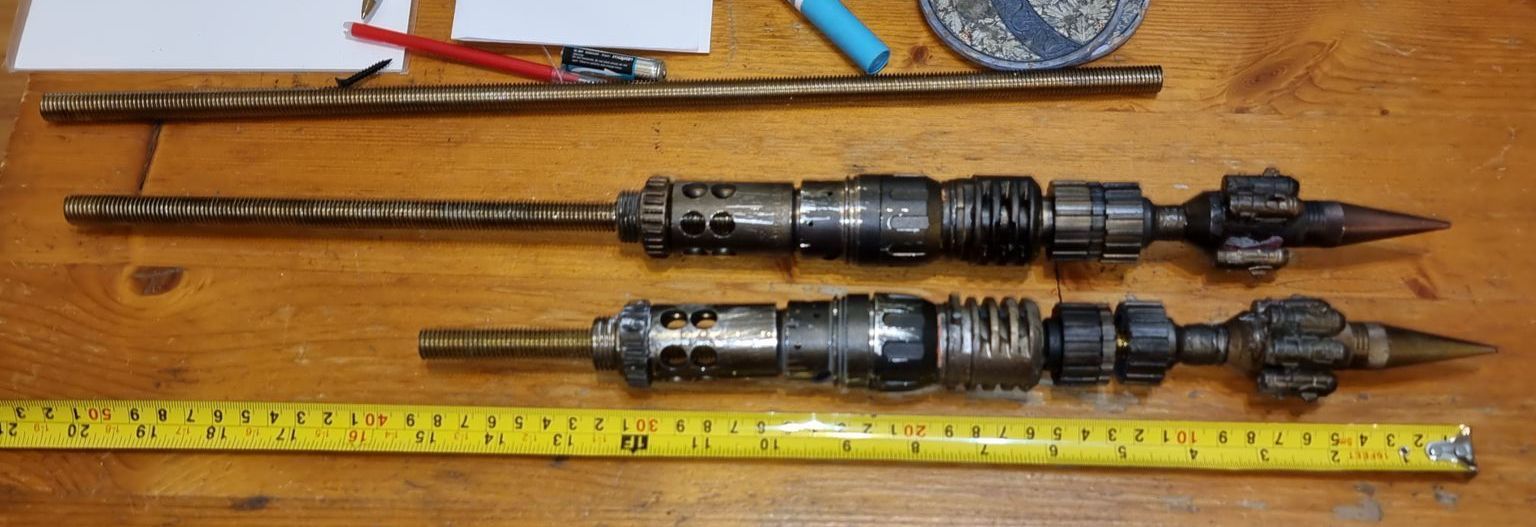
Machining the First Thread Bar
To try and work out a rough length the thread bars needed to be, I tried various combinations of components alongside the 12mm thread bar.
Some components could slide along the thread bars as were loose with a wide enough inner diameter, others would need drilling and tapping with a tread carving tools I tried first using my mitre saw which was very louds before trying the Finn Multi Master Multi tool with metal cutting blades.
The latter took much longer but did a far neater cut. This required less grinding to clean the ends up.
As the griding heated up the thread bar I wet them down with water to cool.


Drilling Through Components
I broke off the brush handles, tried my best to drill through to 10mm then use the tapping tool for a 12mm inner thread.
Stepper drill bits were used to do this gently as the components were fragile.
Sprayed some of the components as well as drilling and tapping before trying various component combinations to see what worked. The brush looked promising.


Hexaonal Shaped Ring
One of the components was a vertical griped ring from a multi screwdriver.
These was originally a rubbery material which wrapped around one of the metal components which had a hexagonal end.
Being flexible, this fitted well over the irregular shaped component.
Unfortunately, what was found that when painted the paint does not bond but flakes off easy as the paint is not flexible.
The first solution was to make a silicon mould of one of these rings and resin cast copies which then could be painted more effectively with paint that sticks to the solid material.
The problem being that as the original material was flexible it stretched to shape and size. Hard cast resin does not. it stays round and small so does not fit.
I tried using a powerfile on the metal component but it was too tough.
A simple solution, that did require new moulds, was to take out the cast or the ring early, before it sets hard when a flexible cheesy soft material consistency that could stetch and flax to shaper, them bull it to the part which then adapts to the shape of the component then sets hard into a hexagonal shape. This worked.


Adding Graphite Powder
It was around here I started to add graphite powder both to the resin and the mould.
This made the cast components dark grey throughout and shiner so less paint would be needed and damage did not show up as white patches.


Component Combination
With the components prepped I tried a variety of component combinations, to see what could work best for the transmitting communication towers. This included designs with support cables coming up from the bases which looked more solid and stable. This could include elements like electroluminescent string for a more sci-fi look.
I was also trying to work out the best length for the towers that looked cool and was practical.


Painting
The components were given the basic painting of primer, black, then washes of aged cold, copper metallic paint and Dirty Down Rust, Dirty Down Khaki and Dirty Down Black.


Continuing Component Combination
With the components painted I then carried on trying combinations to refine the order and see how they looked when more metallic. The brush looked particularly good and technical with what looked like many aerials


Shortening the Tower
Much as it looked good to have really tall transmitters with all the components, especially the brushes, they also have to be solid and strong, not just when upright, but when the unit was folded open. The length give too much leverage to beat the tower prop.
The tower prop also needed to be able to be handled easily and be placed in the likes of cars and boxes so decisioned had to be made to shorten the length and that included losing the brushed being one of the longest parts.


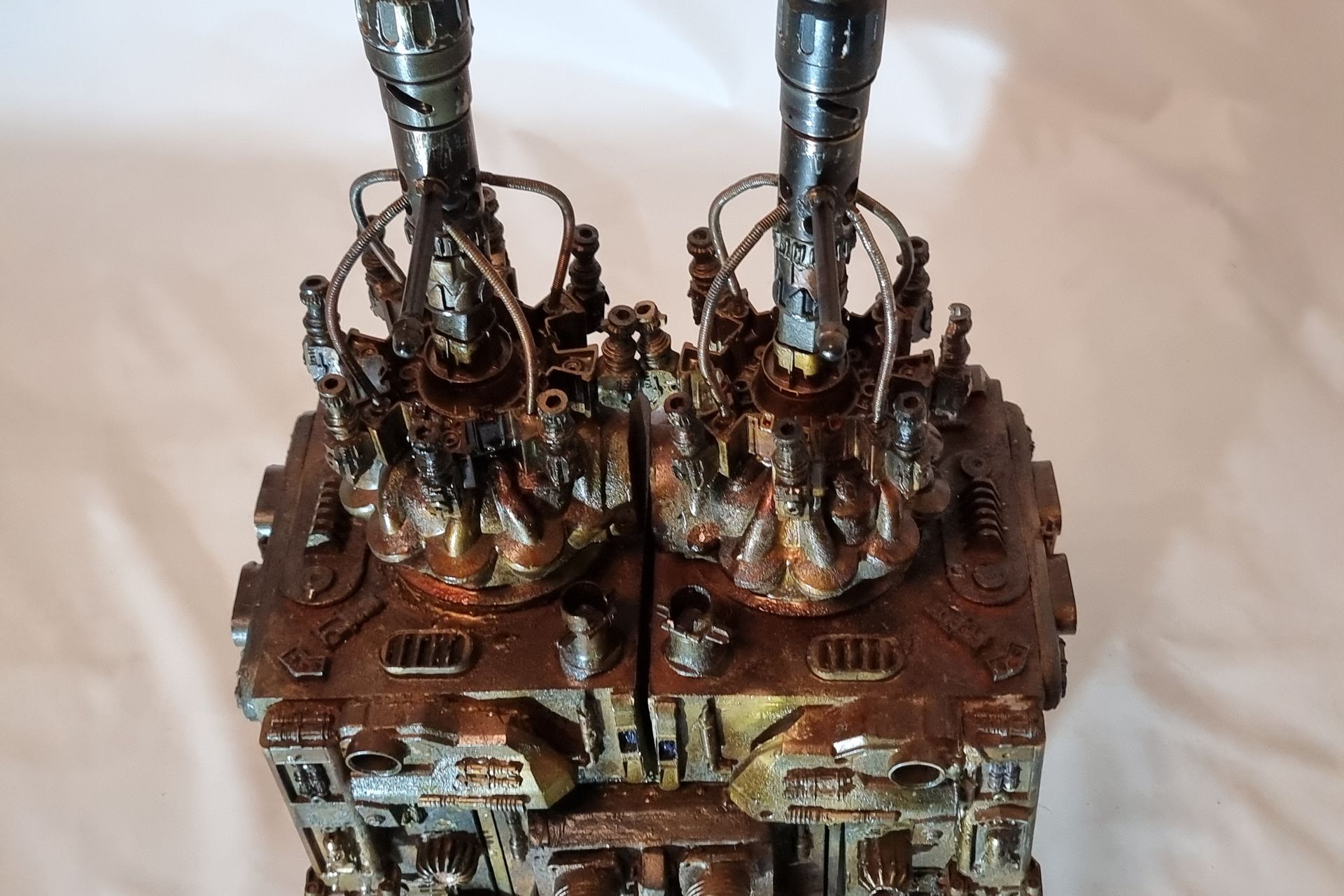
Additional Kit Bashing
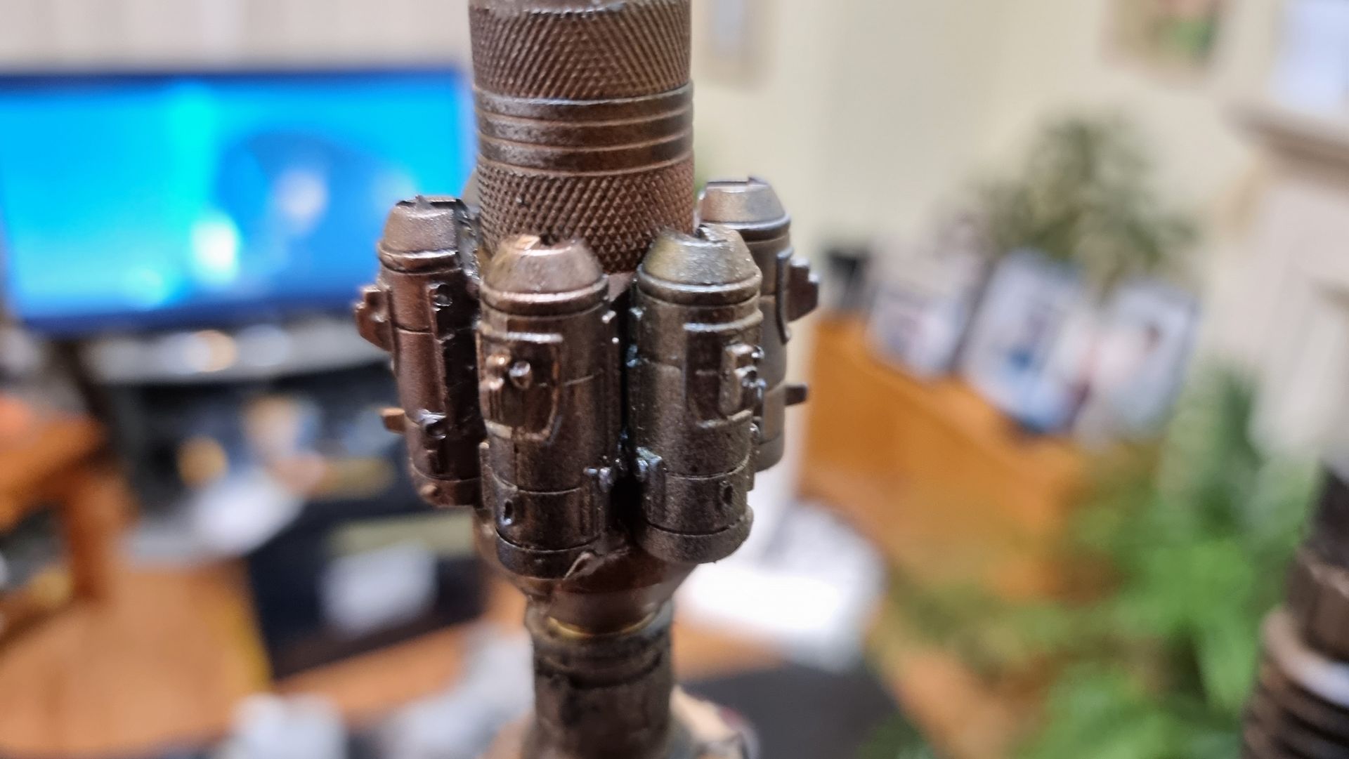
Additional kit bashing was added to the towers to enhance the look adding war hammer like tanks to the hexagonal tower tops sections and adding Warhammer guns or cannons to the Nerf Multi shop bases all pointing up like they could send out converging energy pulses like the Death Star planet killing cannon.


Kitbash Components Reinforcement with Rivets and Resin
Problem to Solve
One problem that came up rapidly is all these kits bashed, up pointing gun like attachments to the transmitter towers were not well bonded and broke off with the slighted knock and only superglued, easy to catch on and leaver off or knock off with sheer forces.
A system needed to be incorporated to structurally attach these parts not just glue them.
More importantly the Nerf gun cartidge disk they were to attach too was:
- Fragile
- It was a crucial part that would be very had to replace, I only had one spare.
- Too costly to mould
- I was reluctant to use screws, plus it would be difficult to get the right size.
- Also, screws would look awful.
Problem Solving Solution - Pop Rivets
Pop rivets seem to be the solution with small holes drilled through then the rivet inserted and pulled tight, this seems to work and look good too when the rivets were pre painted.
I first tried this with 4 mm steel rivets for a grip distance or around 16mm then 25mm.
This gave a mechanical structural joint not just stick on but I ran into probelms.


Rivet Gun Problems - Rivet Jams and Strenght Needed
On youtube videos rivet guns seems easy to use, I had an old Wilco Discount shop hand rivet gun so I thought I would get some 4mm x 20 mm pop rivet which I had spray painted but could not get my rivet gun working. I could not pull or pop my rivets so thought I would get a better one so tried the likes of:
- Screwfix Direct
- Tool Station
- B& Q
- Local Hardware stores
- Tradepoint
Without luck.
Got the best one I could find locally, a Stanley 6-R77 heavy duty with swivel head model which seemed more solidly from Machine Mart which seemed to sell more professional kit, built but still no luck cutting the rivets when in place
Problem Solving Solution - Switch to Aluminium Rivets
Went on various forums before learning that the issue may be me using Stainless Steel Rivets so I tried 4mm x 25mm aluminium rivet, they seemed to work. Black Rivets also helps avoiding the need to paint them.
Problem Solving Solution - Future Equipment - Electric
Due to difficulties with the huge amount of strenght needed in hands to use the hand riveters and frequency or jamming, I hope to replace these with electric riveters when I can afford them.


Strengthening the Communication Tower Base Stability Issues:
History
When I created the towers, they were done simply by gluing components together and thus was rubbish that fell apart.
No spine and all parts glued on top of the Dyson motors on top of the wing box ends.
To add a spine and root it deep inside through the Dyson motors and into the wing box end below this was drilled though with long bits.
The Problems After Adding Spine - Wobbly Base
The inside of the Dyson motors and wind box cavities below were all hollow, so not much to hold the shaft, more so the end which could wobble around and pivoted in the Nerf disk on top of the Dyson motors creating a stress point in fragile material.
None of this was solid. The entry point of the thread bar in components acted like a pivot made from very weak breakable Nerf Polystyrene parts.
The Dyson Motors themselves had problems staying stuck to the main body. As the towers wobble or were pressurised to the side with sheer forcessuch as laying in the crate this unstuck the bas of the Dysons motors so it was just the shaft holding them in place.

The Problems After Adding Spine - Wobbly Base
The inside of the Dyson motors and wind box cavities below were all hollow, so not much to hold the shaft, more so the end which could wobble around and pivoted in the Nerf disk on top of the Dyson motors creating a stress point in fragile material.
None of this was solid. The entry point of the thread bar in components acted like a pivot made from very weak breakable Nerf Polystyrene parts.
The Dyson Motors themselves had problems staying stuck to the main body. As the towers wobble or were pressurised to the side with sheer forces such as laying in the crate this unstuck the base of the Dysons motors so it was just the shaft holding them in place.
Loose Parts Falling Off
Various kit bash parts kept falling off as only glued on. The cylinders as the top often as handled they were held to twist the communication towers rubbing them off and the the up pointing gun like parts on the nerf disk
Strengthening the Tower Base Stability Solutions:
Strengthening the Tower Base Problem Solving Technique 1 :
Movement Preventing Cavity Foam Filling
The base for the towers needed strengthening to create a strong foundation and two methods were used here.
The problem was that the connection parts above the Dyson motors and the wing boxed ends.
- To increase the length of the thread bars mentioned above to go deep inside into the wing boxes.
- As this was a retrofit, I had no intension to cut open the boxes or Dyson Motors. This would probably wreck things.
- To create a firmer hold by stuffing the end of wing empty boxes and hollow caverns of Dyson motors.
i thought fill with some sort of expanding materials to fill the gaps. - I tried to do this with expanding insulation foam from a can.
- Whilst the foam was not very had when set it would be firem enough to stop the shafts wobbling all over the place and make for a firmer base.


Weak Communication Transmitters Problem Solving - 2
Kit Bash Connection Component Strengthening & Backups
Just above the Dyson motors was a set of interlocking connection parts taken from Nerf guns. Given these were places at a key stress point and could not be replaced as from certain Nerf gun parts, that had been purchased from Ebay, second hand, and were most likely discontinued it seemed wise to make moulds so replacement and spares could be made.
I also could see these parts where fragile and the long square part with the crown to the right here was where the spike entered and at the most stressed point. Being hollow it was also not holding the shaft, so I tried to make a new mould that filled in the inside to make a solid part from my resin. This I could then drill through and add a taped interior screw thread.
As these were complex fully 3D shapes with overhangs and internal cavities 2-part moulds were required. Plastaline was used to mask off the lower halves of the mould making blocks, whilst the first part of the moulds was filled with silicon and when set quick release was spray was applied before filling the second half with silicon.
These could then be filled with fast cast resin.
I incorporated a hole punch indent to help drilling in the design of the parts


Weak Communication Transmitters Problem Solving 3 - Resin Fill Plug Reinforcement
However nervous that the upward pointing kit bash gun parts were only held by 1mm or ABS from a nerf gun Cartridge I came up with the idea of filling the compartment where the rivet had gone through with resin. I also looked at use of Epoxy.
That way the part the rivet as watched had the head immersed in hard resin and not just thin plastic do less likely to snap off a chuck of the disc if caught on something.
As well as being much stronger the load was spread over the whole disc.
I tested the theory first with an orange prototype to see if it would work.
This also solidified the support cables bond with the disc.


Weak Communication Transmitters Problem Solving 4 - Riveting on the Dyson Motors
What was found when using the Tower prop with the transport case the communication towers were loosened to wobble with the Dyson motors detaching from the tower body box ends so it’s only the shaft holding things together.
I tried adding a layer of foam to give some flex and various glues but nothing lasted. I have how inserted rivets around the base of the Dyson motors with holes at roughly a 45 degree down.
These were spray painted to blend in.
I found I needed at least 40mm rivets to get through the layers and at an angle.
I also had the problem of the drill head damaging the Dyson moters bumping in whilst spinning as the drill bits broke through.
This I just painted over and it adds to the wear and tear look.


Support Cable Development and Problem Solving
Adding the Support Cables
At first cutting and adding these spring cables made from drain clearing tools looked like it would be easy but turned out these were a total pain as due to their springing, flexible tendency to vibrate nature they were all but impossible to cut.
Tools that failed included my:
- Mitre Saw
- Wire Cutters
- Nibler Tool
- Jig Saw
- Various attachments on my Finn Multi tool
The only thing that worked was my angle grinder when the cable was held in the workbench and then right up against the vice in the table top.
The only thing that worked was my angle grinder when the cable was held in the workbench and then right up against the vice in the table top.
I then levels ed and rounded them off with my powerful which worked better than the disc belt sander.
These were then painted as usual with the dirty down and metallic spray paints.
The original plan had been to permanently attach the cables to act as working supports but if I did that, I would not be able the unscrew the towers for safety in transport and storage.
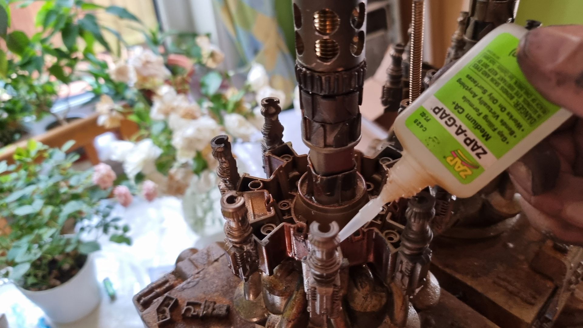
The base ends fitted nicely into the Nerf multi shot disc above the Dyson cyclone motors in the holes.
These where then glued into place with I think superglue and activator.
The other end just clipped securely into the doles on the tower component I think originated from a blow torch majorly enhancing he look


Extending The Tower Support Cables March 2025
Problems to Solve
- It was found that the support cables were too short as can be seen from the first photos.
- This was much more apparent when twisting the handles added later to fit in the crate.
- I only needed and extra 10 - 15 mm but the issue was how.
- The cables were just held on the coles on a cylindrical component that looked like it came from a blow torch.
- However point on the cables I needed the extension joint is where all the sheer stress was focused due to bending under tension so the bond has to be super strong and structured or it would just snap.
- None of the glue techniques would work.
- Attaching some form of tube over the end would looks bad and be very obvious.
- As these were made from spring tubes (Drain cleaner rods.) that meant that they were hollow and flexible.
- Alao a major problem was their bottom ends where embedded in resin making them impossible to remove and replace without destroying the holding disc
Solutions
- To do this I needed very short lengths of the drain cleaning spring cable, only around 10mm.
- This was way to dangerous and impractical to cut with my mitre saw.
- I did try with an angle grinder but this gave a very rough messy cut.
- Thus, I moved to using my multi tool which gave a far cleaner cut.
- Thus, was not held well in the vice and prone to moving.
- I tried to fix this by encasing the spring cable in tissue.
- Once I had the spring cable cut to length, I cut lengths of 3mm mild steel garden wire as a spine.
- These were about 3 cm long.
- This was inserted in the tubes to make a joint and then this was stuck with superglue.
- The result was a flexible strong extension joint.